electrical panel wiring diagram pdf
Summary
Get your free electrical panel wiring diagram PDF here! Detailed schematics for safe and efficient installations. Download now!

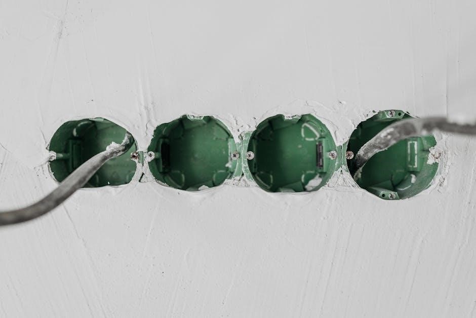
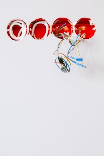
Electrical panel wiring diagrams are detailed blueprints illustrating the connections and components of an electrical system‚ essential for installation‚ maintenance‚ and repairs of industrial and residential setups.
What is an Electrical Panel Wiring Diagram?
An electrical panel wiring diagram is a detailed blueprint or schematic representation of an electrical system’s connections‚ components‚ and circuits. It visually illustrates the wiring layout‚ power distribution‚ and control functions within a panel. This diagram is essential for electricians and engineers to understand the system’s operation‚ ensuring safe and efficient installation‚ maintenance‚ and troubleshooting of electrical systems in industrial‚ commercial‚ and residential settings.

Importance of Electrical Panel Wiring Diagrams
Electrical panel wiring diagrams are crucial for the safe and efficient operation of electrical systems. They serve as a central reference for electricians‚ engineers‚ and technicians‚ ensuring proper installation‚ maintenance‚ and troubleshooting. These diagrams reduce the risk of electrical errors‚ enhance system reliability‚ and simplify compliance with safety standards. By providing a clear visual representation of the system‚ they act as essential tools for diagnosing issues and planning upgrades‚ making them indispensable in both residential and industrial settings.
Understanding Electrical Panel Wiring Diagrams
Understanding electrical panel wiring diagrams is crucial for identifying components‚ tracing connections‚ and ensuring safe‚ efficient system operation‚ as detailed in PDF resources.
Key Components of an Electrical Panel Wiring Diagram
A wiring diagram typically includes circuit breakers‚ fuses‚ buses‚ terminals‚ and connections. It outlines power distribution‚ control circuits‚ and grounding systems‚ ensuring safe and efficient electrical operations. Standard symbols represent components like switches‚ motors‚ and transformers‚ while labels clarify wire types and ratings. These elements collectively provide a clear‚ detailed visual representation of the electrical system‚ aiding technicians in installations‚ troubleshooting‚ and maintenance.
How to Read an Electrical Panel Wiring Diagram
To read a wiring diagram‚ start by identifying the legend or key‚ which explains the symbols used. Trace circuits from the power source to devices‚ following wires and connections. Focus on main components like circuit breakers and fuses. Understand the flow of electricity and how switches or controls operate. Look for labels indicating wire types‚ sizes‚ and ratings. This systematic approach helps in troubleshooting‚ installations‚ and ensuring compliance with safety standards.
Types of Electrical Panel Wiring Diagrams
Electrical panel wiring diagrams include single-line‚ elementary‚ and control circuit diagrams‚ each providing varying levels of detail for understanding and maintaining electrical systems effectively.
Single-Line Diagrams
Single-line diagrams are simplified representations of electrical systems‚ showing key components like transformers‚ generators‚ and loads. They use standardized symbols to depict power distribution paths‚ making it easier to understand system layouts at a glance. These diagrams are essential for engineers and electricians to plan‚ install‚ and troubleshoot electrical panels efficiently. By focusing on major elements‚ single-line diagrams provide a clear overview of power flow and connections‚ ensuring safe and effective system management.
Elementary Diagrams
Elementary diagrams provide detailed representations of electrical circuits‚ focusing on the functional logic of components such as contactors‚ coils‚ and terminals. These diagrams are crucial for understanding and troubleshooting control circuits in industrial settings. They often include standardized symbols and notations‚ making them accessible to engineers and technicians. Elementary diagrams are particularly useful for designing and verifying the wiring of complex systems‚ ensuring accurate connections and reliable operation of electrical panels.
Control Circuit Diagrams
Control circuit diagrams outline the electrical connections and components of control systems‚ detailing how devices interact. They simplify troubleshooting by showing power and signal flows. These diagrams are essential for understanding automation and industrial systems‚ often used by technicians to identify faults and optimize operations. Control circuit diagrams ensure efficient and safe functioning of electrical panels in various applications.

Common Symbols and Notations
Standard symbols represent components like circuit breakers‚ fuses‚ and wires‚ ensuring clarity in electrical panel wiring diagrams for accurate interpretation and installation of electrical systems.
Standard Symbols in Electrical Wiring Diagrams
Standard symbols in electrical wiring diagrams represent components like circuit breakers‚ fuses‚ wires‚ and switches. These symbols are universally recognized‚ ensuring clarity and consistency in interpreting electrical systems. They include graphical representations of power sources‚ grounding points‚ and protective devices. Understanding these symbols is crucial for electricians and engineers to accurately design‚ install‚ and troubleshoot electrical panels. Standardization ensures safety and compliance with electrical codes‚ making diagrams accessible across different regions and industries. These symbols are essential for maintaining precision in electrical documentation and practices.
Understanding Circuit Breakers and Fuses
Circuit breakers and fuses are essential components in electrical panels‚ protecting systems from overcurrent conditions. Fuses are sacrificial devices that melt when excessive current flows‚ while circuit breakers trip and can be reset. Both prevent damage to wiring and equipment by interrupting the circuit. Understanding their operation is critical for safe electrical panel maintenance. Fuses provide permanent protection‚ requiring replacement after blowing‚ whereas circuit breakers offer reusable protection‚ making them ideal for frequent use in industrial and residential settings.

Safety Considerations
Always isolate power supplies before working on electrical panels and follow proper safety protocols to prevent shocks or accidents. Use personal protective equipment and ensure safe practices.
Safe Practices for Working with Electrical Panels
Working with electrical panels requires strict adherence to safety protocols. Always disconnect power supplies before starting work and verify de-energization using appropriate tools. Wear personal protective equipment‚ including insulated gloves and safety glasses. Ensure proper ventilation and avoid overloading circuits. Follow lockout/tagout procedures to prevent accidental energization. Keep emergency contact information handy and know first aid procedures for electrical accidents. Regularly inspect tools and equipment for damage. Never attempt repairs without proper training‚ and always refer to the wiring diagram for guidance.
Emergency Procedures for Electrical Accidents
In case of an electrical accident‚ immediately isolate the power supply and avoid direct contact with live components. Use non-conductive tools to release individuals from electrical contact if safe to do so. Call for professional help and locate the nearest first aid kit. Administer basic first aid‚ such as CPR if necessary‚ until medical assistance arrives. Ensure the area is safe and prevent unauthorized access to the electrical panel until repairs are completed.

Creating an Electrical Panel Wiring Diagram
Creating an electrical panel wiring diagram involves gathering circuit details‚ using specialized software‚ and ensuring accurate representation of components and connections for safe and efficient installations.
Tools and Software for Diagram Creation
Various tools and software are available for creating electrical panel wiring diagrams‚ such as AutoCAD‚ SolidWorks‚ and specialized electrical CAD programs. These tools provide libraries of symbols‚ templates‚ and automation features to streamline the design process. Additionally‚ software like ETAP and EPLAN offer advanced functionalities for circuit design and simulation‚ ensuring accuracy and compliance with industry standards. They also support PLC programming and panel layout design‚ making them essential for both novice and experienced engineers.
Steps to Design a Wiring Diagram
Gather circuit information‚ including components and connections. Plan the sequence of connections and choose the appropriate diagram type. Use specialized software with standard symbols to represent components. Ensure compliance with safety standards and local codes. Draw the diagram using standard symbols for components like switches and circuit breakers. Label all components and connections clearly. Review and validate the diagram for accuracy‚ simulating the circuit if possible. Test the wiring against the diagram to ensure correct and safe connections.
Practical Applications
Electrical panel wiring diagrams are crucial in industrial control panels‚ residential wiring‚ and commercial setups‚ ensuring efficient power distribution and system control while maintaining safety standards and compliance.
Industrial Control Panels
Industrial control panels are critical systems used in manufacturing and automation‚ relying on detailed wiring diagrams for precise power distribution and control. These diagrams outline circuit layouts‚ ensuring efficient operation of machinery and compliance with safety standards. They include components like circuit breakers‚ contactors‚ and relays‚ essential for managing high-power industrial processes. Properly designed diagrams enable troubleshooting‚ maintenance‚ and upgrades‚ ensuring uninterrupted production and adherence to regulatory requirements‚ making them indispensable in modern industrial settings.

Residential and Commercial Wiring
Electrical panel wiring diagrams are crucial for residential and commercial setups‚ detailing circuit layouts‚ power distribution‚ and safety measures. They ensure compliance with local codes‚ guiding installations and repairs. These diagrams highlight components like circuit breakers‚ outlets‚ and lighting systems‚ aiding electricians in troubleshooting. Proper wiring ensures efficient power delivery and safety‚ preventing hazards. Diagrams also outline RCD and grounding requirements‚ essential for protecting people and equipment in both homes and businesses‚ ensuring reliable electrical systems.
Best Practices for Wiring Diagrams
Use standardized symbols‚ clear labels‚ and organized layouts for wiring diagrams. Ensure accuracy and legibility‚ and validate designs through rigorous testing to guarantee reliability and safety.
Labeling and Organization
Proper labeling and organization are crucial for wiring diagrams. Use clear labels for wires‚ components‚ and terminals to ensure easy identification. Maintain consistent terminology and formatting across the diagram. Organize components logically‚ grouping related devices together. Include wire numbers and component IDs to simplify tracing connections. Use standardized symbols and color codes for clarity. A well-organized diagram reduces errors and facilitates installation‚ maintenance‚ and troubleshooting. Ensure the layout is neat‚ with minimal crossing wires‚ to enhance readability and professional presentation.
Testing and Validation
Testing and validation ensure the electrical panel wiring diagram is accurate and functional. Verify each connection against the diagram to confirm compliance with design specifications. Conduct visual inspections to check for proper labeling and organization. Perform electrical tests‚ such as continuity checks and voltage measurements‚ to ensure circuits operate safely and efficiently. Validate the diagram against industry standards and best practices. Any discrepancies must be documented and corrected to prevent potential hazards and ensure reliable system performance.
Resources and Further Learning
Explore free PDF resources‚ manuals‚ and guides for electrical panel wiring diagrams. Utilize recommended software tools for designing and interpreting diagrams to enhance your understanding and skills.
Free PDF Resources for Electrical Wiring Diagrams
Access free PDF resources for electrical wiring diagrams‚ offering detailed schematics and guides for understanding and designing electrical systems. These documents provide comprehensive overviews of circuit layouts‚ component connections‚ and control functions‚ serving as invaluable tools for electricians‚ engineers‚ and students. Resources like “266219078-mcc-panel-wiring-diagram-and-panel-ga-sample.pdf” and “Electrical Wiring Diagram PDF Manual Book” are widely available for download‚ ensuring practical knowledge for installation‚ maintenance‚ and troubleshooting electrical panels and systems.
Recommended Software and Tools
For creating and analyzing electrical panel wiring diagrams‚ tools like AutoCAD‚ ETAP‚ and Siemens NX are highly recommended. These software programs offer advanced features for designing precise layouts‚ simulating circuits‚ and generating detailed schematics. Additionally‚ specialized electrical CAD software provides libraries of symbols and tools tailored for wiring diagrams. PDF guides‚ such as the “Industrial Control Panels and Electrical Equipment” manual‚ are also valuable resources for understanding and implementing electrical panel wiring effectively.